Rear LED Brake and Turn Signal mod


lwclancers

New Member
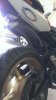
This weekend I will be partaking in my personal implementation of this mod:
http://www.600cc.org/forum/f91/rear-fender-led-brake-light-29748/

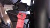
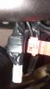
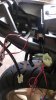
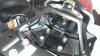
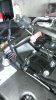
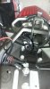
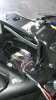
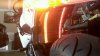
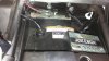
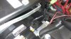
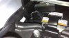
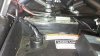
I got the amber LEDs in the mail this week, to go along with the red. I posted some in the thread above as well, last post indicates the wiring schematic I need to tap into the stock brake and turn wires.

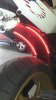
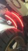
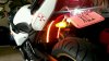
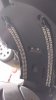
I plan on running the red LEDs as done here, all the way down. I am still deciding on the amber...either run them side by side the whole way, or, cut the amber so they are shorter (50-75%). Why? I believe that while braked or braking (thus engaging the red LEDs) that a flashing yellow of the same size right next it, may not be as eye catching as a light flashing of a shorter length...I think itll be more clear and engaging/noticeable. I'd like to hear others thoughts though.

I may even place the amber a little further away, not right against the red LEDs, but would need to relook at placement. Also, the routing whole in the little dimples would work better if they are side by side. If I place them someplace else I'd likelt need another entry point into the rear. So will see!

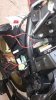
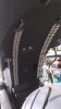
I have the stronger tape, circuit (even if not totally necessary), RTV, etc. Just need time to put it all together. More to come.
 

lwclancers

New Member
Very similar to the thread above. In this set, I drilled holes through the dimples in the rear. I ran the 2 sets of wires on each side through (I heat shrink and wrapped them in electrical tape through the hole). I then filled the dimples with plenty of black RTV adhesive silicone, also some on the inside...no water getting through there! Ran a small bead down each side of the lights too. It was messier than I thought, if I had to do it over again I would have just done the holes and been done with it. Especially after replacing the thin 3M tape that came on the lights with the more substantial 100lb outdoor tape.

As noted in a post above, I agree and think exposed LED can at times appear tacky, so I went ahead and ran the signals the same length as the brakes. When off (in a couple of posts down) it doesn't looks too bad or stand out as being weird/tacky.

NOTE: Also, if you notice, the under seat portion as some indentations that are NOT uniform on both side. On the right side, the indentation is lower, and pushed further to the edge. I had to shave off a very small protruding nipple off with an exacto knife. This hole was them covered completely by the light strip. You can vaguely notice a matching protruding nipple on the left side still. So the lights are a little further to the edge on the right than on the left. Its not really that noticeable though.

NOTE 2: I also drilled some small holes on both sides of the inside plastic box to help rout the wires to the right hand side where ther stock wiring was.
 

Attachments

Last edited:

lwclancers

New Member
I then began taping sections of wire I was routed things to the right side. With the small right side/rear plastic removed you have access to all the rear plugs. As noted in the thread above, I had found another thread highlighting the wiring needed here:
5. You now have full access to the tail lighting connectors:
A 3 Position 090 HM Connector (Wires: Yellow = Brake Light, Blue = Tail Light, Black = Ground)
A Black Nippon -Tanshi’s 3P Turn Signal Connector (Wires: Brown = Left Signal Light, Black = Ground)
A Grey Nippon -Tanshi’s 3P Turn Signal Connector (Wires: Green= Right Signal Light, Black = Ground)
2 Bullet connectors, 1 with Blue wire in and black wire out (positive), the other with Black Ground wires.

SO the yellow for the brake, brown for the left signal, green for the right signal. I then decided to go this route: I used 3 fuse holders, one for each hot lead. Why? Well, Im not entirely sure the signals or tail will pass inspection in VA. Im pretty sure the brakes will, but the signals are less than 9 inches apart, which is what they said they had to be. So with the 3 fuses, I can simply pull the fuse and they will be inoperable... while the main hot they tap into will still be on.

Each fuse was tapped in using a quick connect. I know I could have used those too, but pulling a fuse is a heck of alot faster...plus I taped everything up after wards.

Instead of wiring in all the ground (2 brakes, 1 each for the turns) I put them all together, and ground them to one of the nuts using a ring connector. The but sits right on top of the rear seat support bar in front of the tool storage area and is connected to the chassis. This approach really worked out well.

I way over-engineered this thing, but its functional and has its purpose. :)
 

Attachments

Last edited:

lwclancers

New Member
And the finished product. Off, on, and a couple of video grabs from a video with the brakes engaged and signals on on each side. Its a lot better in person than on video or pics.

I should have tried to get a video still of the signals w/o the brakes.

I think it came out well. Id give myself maybe an 8/10 for execution. I could have done a few things better, but in the end Im kind of proud of myself (wiring makes me nervous haha).
 

Attachments

Last edited:

lwclancers

New Member
Finished and updated :)
 

CTK2609

New Member
I think it came out well. Id give myself maybe an 8/10 for execution. I could have done a few things better, but in the end Im kind of proud of myself (wiring makes me nervous haha).
Nice job... thinking of doing the same. Anything to increase visibility when stopping...
 

lwclancers

New Member
Reviving this one. So I installed my led extra brake lights and extra signals last fall. When I did I installed an inline fuse for each signal and the brake. I did so so I could remove the fuse from the block to deactivate the extra lights for VA inspection. Well I just pulled the fuse for each line, and the damn things still light up lol. Shouldn't they no longer work? I swear I tested this when installing. Now I fear I might need to cut the line and repatch the original wiring just to get these lights turned off.

Tell me I'm just being dumb!

Sent from my HTC6435LVW using Tapatalk
 

Scott_Thomas

Insert title Here
Elite Member

lwclancers

New Member
The pics are earlier in this thread :) yes, ran an inline to each signal and one to the brake. When I pull the fuse and activate each light, the light on the inline fuse flashes. I'm so confused, I don't want to start this whole thing over

Sent from my HTC6435LVW using Tapatalk
 

lwclancers

New Member
Disconnected the grounding wire and now Im good to go, no lights/signal. Duh. Sigh. :)
 

Scott_Thomas

Insert title Here
Elite Member


Top