So I finally got time to do this install. Got the stuff off Revzilla.com.
The only con to this product is that the cable was shorter than I would have liked but I got it to work. If needed you could always splice in some new wires.
If this is too in depth for some of you guys I apologize but the way I see it you can always skip steps but you can't make them up in between.
Also when I don't designate was side use the side that you want to route the cable. I used the drivers left side as I mounted it on the left side of the handlebar. Another member did a similar install recently:
http://www.600cc.org/forum/f91/how-install-12v-outlet-22391/
Now that everything is apart, take the Powerlet outlet which comes in two pieces(top and bottom). I used the thicker of the two rubber strips that came in the pack.
Powerlet Handlebar Outlet Also Mounts Gadgets(comes with everything in the picture on the powerlet website)
Powerlet 1" RAM Mount Ball(screws onto outlet)
The only con to this product is that the cable was shorter than I would have liked but I got it to work. If needed you could always splice in some new wires.
If this is too in depth for some of you guys I apologize but the way I see it you can always skip steps but you can't make them up in between.
Also when I don't designate was side use the side that you want to route the cable. I used the drivers left side as I mounted it on the left side of the handlebar. Another member did a similar install recently:
http://www.600cc.org/forum/f91/how-install-12v-outlet-22391/
- Disconnect turn signal(one connector)-1 pic
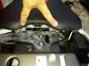
- Take off side fairing(six bolts)-1 pic
- Take off side panel(one bolt, two holders)-1 pic
- Take off both left and right inner side panels. Instructions for this are in the bike's manual but you just pull toward the tail and up after taking the bolt and fastener out(one bolt, one quick fastener for each side)-1 pic
- Take off back seat(use your key
") )
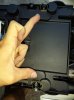
) - Take off front seat(two bolts)-1 pic
- Take off plastic tray(two bolts)-1 pic
- Undo rubber band and take off other plastic tray-1 pic
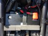
- Disconnect negative terminal first! Then positive.
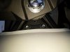
Now that everything is apart, take the Powerlet outlet which comes in two pieces(top and bottom). I used the thicker of the two rubber strips that came in the pack.
- Route the Powerlet cable through the bottom piece and plug in the cable's connector.(This is done before the top and bottom piece is put together to insure a good connection and proper placement of the rubber boot)
- Place the rubber strip in the bottom piece's arc.
- Sandwich the handlebar with the two pieces and use both screws to securely attach the outlet.-1 pic
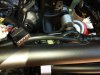
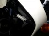
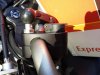
- Tilt the tank up using a box to keep it upright.(two bolts)-1 pic
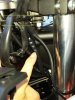
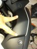
- Route the cable through the cable guider-1 pic
- Route the cable through the factory zip tie
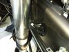
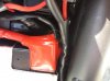
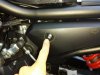
- Route the cable through the hole in the chassis-1 pic
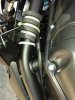
- Zip tie the cable to the chassis next to the other ties and over the cross beam.-1 pic
- Skip other 2 factory zip ties-1 pic
- Route the cable through the factory zip tie-1 pic
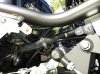
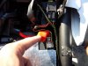
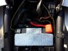
- Snip the (drivers)back left corner of positive terminal connector and connect positive lead to the terminal. Then negative terminal-3 pic
- Put everything back together
Attachments
-
 69.1 KB Views: 63
 -
 82.8 KB Views: 51
 -
 89.6 KB Views: 56
 -
 95.9 KB Views: 47
 -
 84.4 KB Views: 54
 -
 86.6 KB Views: 51
 -
 96.5 KB Views: 59
 -
 91.8 KB Views: 62
 -
 85.5 KB Views: 64
Last edited: